WIFI-Controlled Car
Rekindling the Maker Spirit
Ever since I was young, I have always enjoyed building things myself. My projects ranged from a hot wire cutter used to shape polystyrene (the idea was to build a manual 3D cutting machine) to a mini fan made from reusable components. I was eager to build things, but I lost that eagerness over the past five years.
Recently, I was scrolling on Instagram and came across a video of a young guy named Firmin Forney who built a fully functional bionic arm by himself. That video brought me right back to my childhood. I decided it was time to rekindle that maker spirit. So, I got myself an ESP32 Starter Kit , and here we are with my first project since then, a Wi-Fi-controlled car.
In this post, I am going to walk you through my entire process, from designing the concept to building a working prototype, including assembling, testing, and fixing the issues I encountered along the way.
The Design Process
I knew I wanted to build a remote-controlled car. Given that I had an ESP32 microcontroller, which comes equipped with built-in Bluetooth, Wi-Fi, and GPIO pins to control external components. I had three choices for the controller. I could either control the car via Bluetooth, via Wi-Fi, or by building a dedicated physical controller to connect to the ESP32.
I finally decided to go with the Wi-Fi controller because it allows access to web interface. When configured properly, the car can be controlled from anywhere in the world!
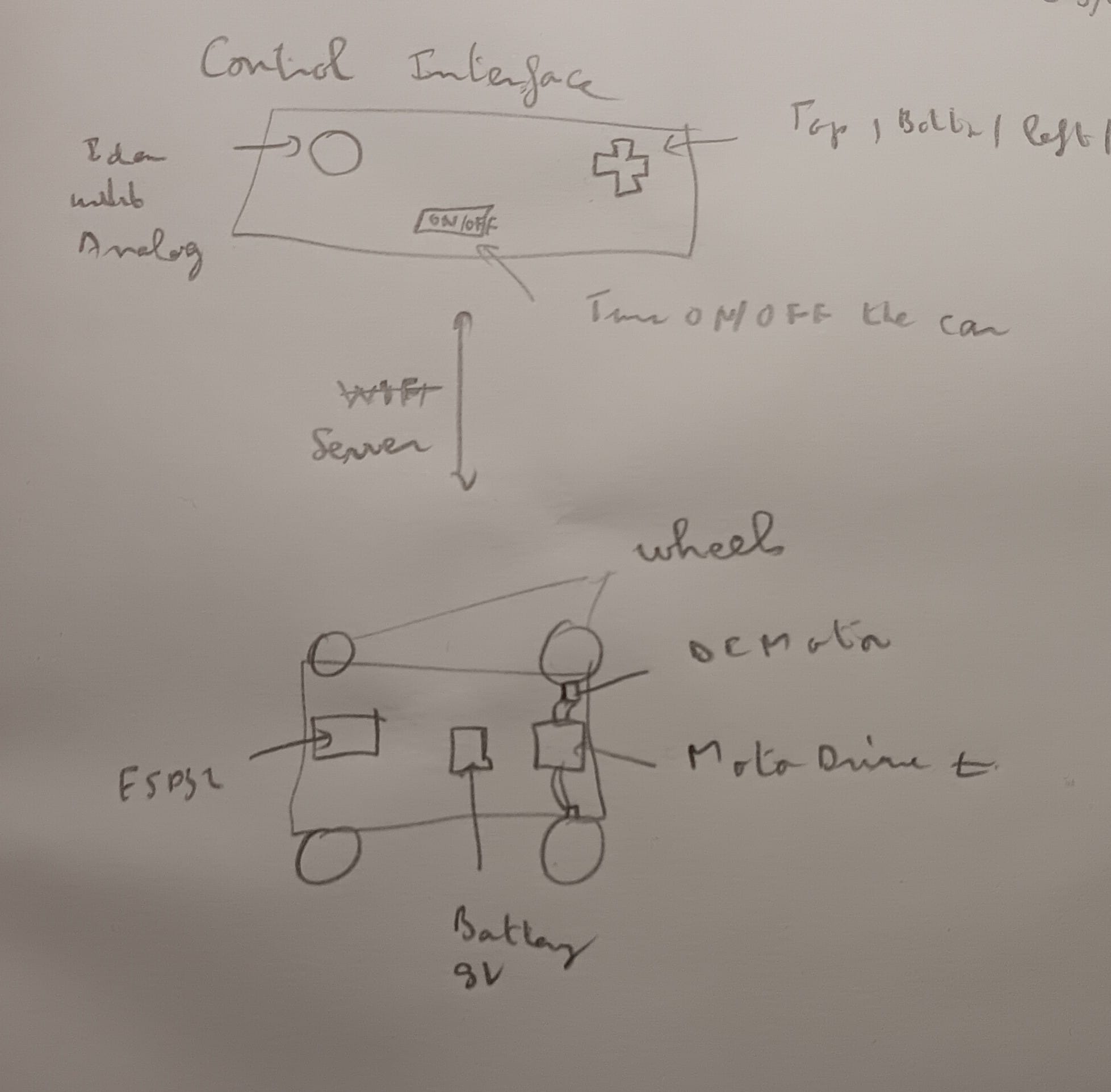
I grabbed a paper and a pencil to sketch out my idea, and here is what it looks like:
Gathering the Requirements
Now that I had a mapped-out idea of what I wanted to build, I listed the required components I would need to make a working prototype:
- 4x DC Motors
- 4x Wheels
- 1x Motor Driver (an L298N in this case)
- 1x Microcontroller (ESP32) — the brain of the system
- 1x Breadboard (830 points)
- 1x 9V Battery
- Some jumper wires for component connections
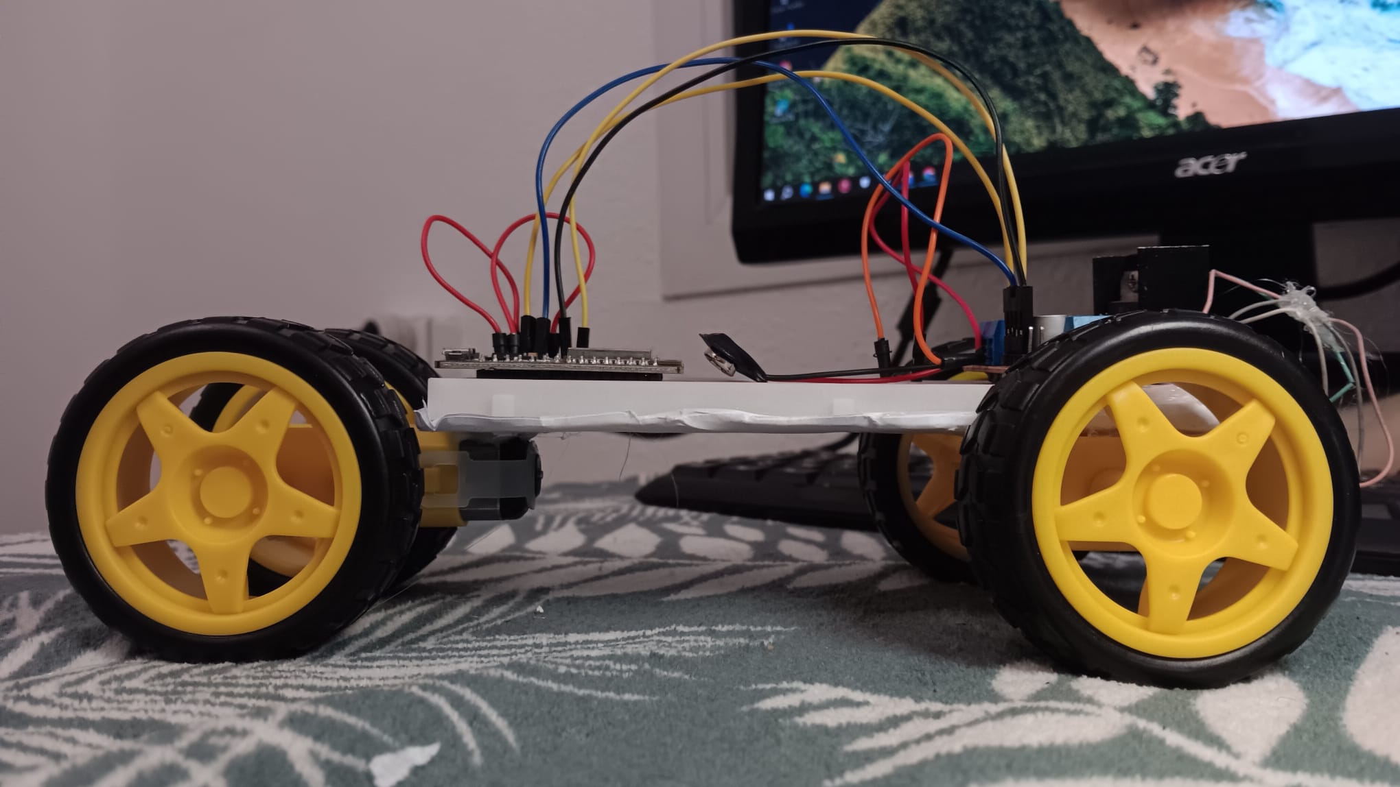
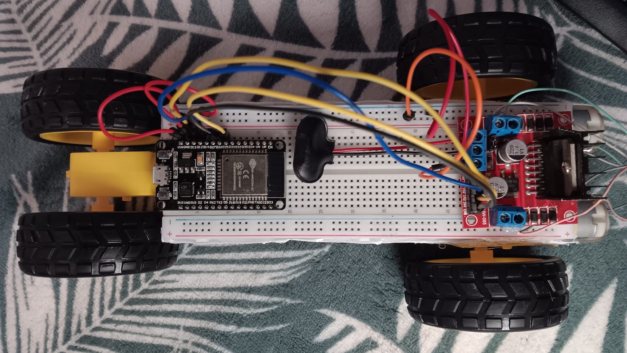
Assembling the Components
To put all the components together, I used a glue stick. I did this to ensure the components could be easily removed and repositioned later if needed.
Initial Testing
Once everything was physically connected, I needed to write some code tailored to my specific setup. I explained the project to Gemini, provided the details of my assembly (specifically telling it which pin went where), and asked it to generate some initial code to test the system.
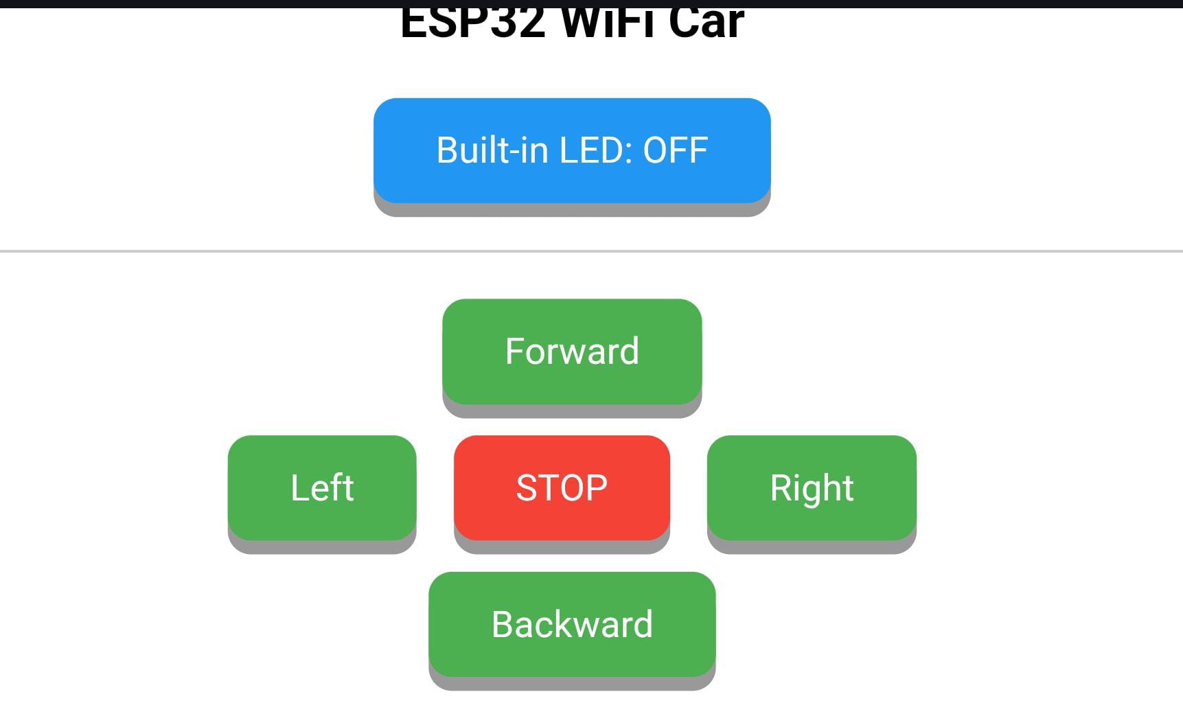
After uploading the code to the microcontroller, as expected, it didn’t work perfectly the first time. The Wi-Fi module did work, I was able to access the web interface hosted by the ESP32 and clearly see the control buttons. However, when I clicked on them, the car didn’t react at all.
And so began the troubleshooting phase.
Troubleshooting and Fixing Issues
Because I hadn’t validated each sub-system before integrating them, I had just put everything together hoping it would work. When it didn’t, I had no idea where the issue was located. To find the problem, my approach was to test and validate each component one by one, starting with the webpage.
First, I wanted to check if the ESP32 successfully received commands when I clicked a button. To do this, I added a new button to the control interface to switch the microcontroller’s built-in LED on and off. Good news, it worked!
Next, I moved on to the microcontroller’s outputs to see if it was successfully sending signals to the motor driver. I moved the jumper wires coming from the ESP32 and connected them to an external LED instead. My hypothesis was simple. If the microcontroller was working properly, sending a movement command from the webpage would turn on the LED. I found that every pin worked perfectly, except for pin 12. Great! I identified an issue I didn’t know existed. Fixing pin 12 didn’t solve the main problem of the whole system not working, but I had successfully validated the ESP32’s functionality.
Then, I moved to the L298N motor driver. I started by testing its output to see if it was sending signals to the DC motors. The result was negative. (Looking back, I probably should have started by testing the input first—logically, if the L298N isn’t receiving a signal, how could it control the motors?).
So, I checked the inputs. As you can see on the L298N, there are 8 pins in total, 4 in the front (IN1, IN2, IN3, IN4) and 4 on the sides (two on the left for ENA, and two on the right for ENB). The ESP32 was connected to the 4 front pins, but I noticed the side pins were open (they didn’t have jumper caps on them). After doing some research (asking AI) about the role of the L298N jumper caps, I understood that they are required to enable the signal to propagate to the outputs. I grabbed two jumper caps, put them in place, and AHA MOMENT! It worked. I was finally able to send commands from the webpage to the car system.
I encountered a few other issues along the way. For example, the commands didn’t match the wheel rotation. If I wanted to move forward, the car turned left. This was a polarity problem because I had connected the DC motors backward. To fix it, I could either rewire the motors or adapt the code. I chose the simpler route, adapting the code.
Another problem was a power supply issue. Whenever I sent a command to move in one direction and then suddenly switched directions, everything stopped working. I discovered this was because I was using the same power source (a single 9V battery) for both the motor driver and the microcontroller. I ended up using two separate power supplies to power them independently.
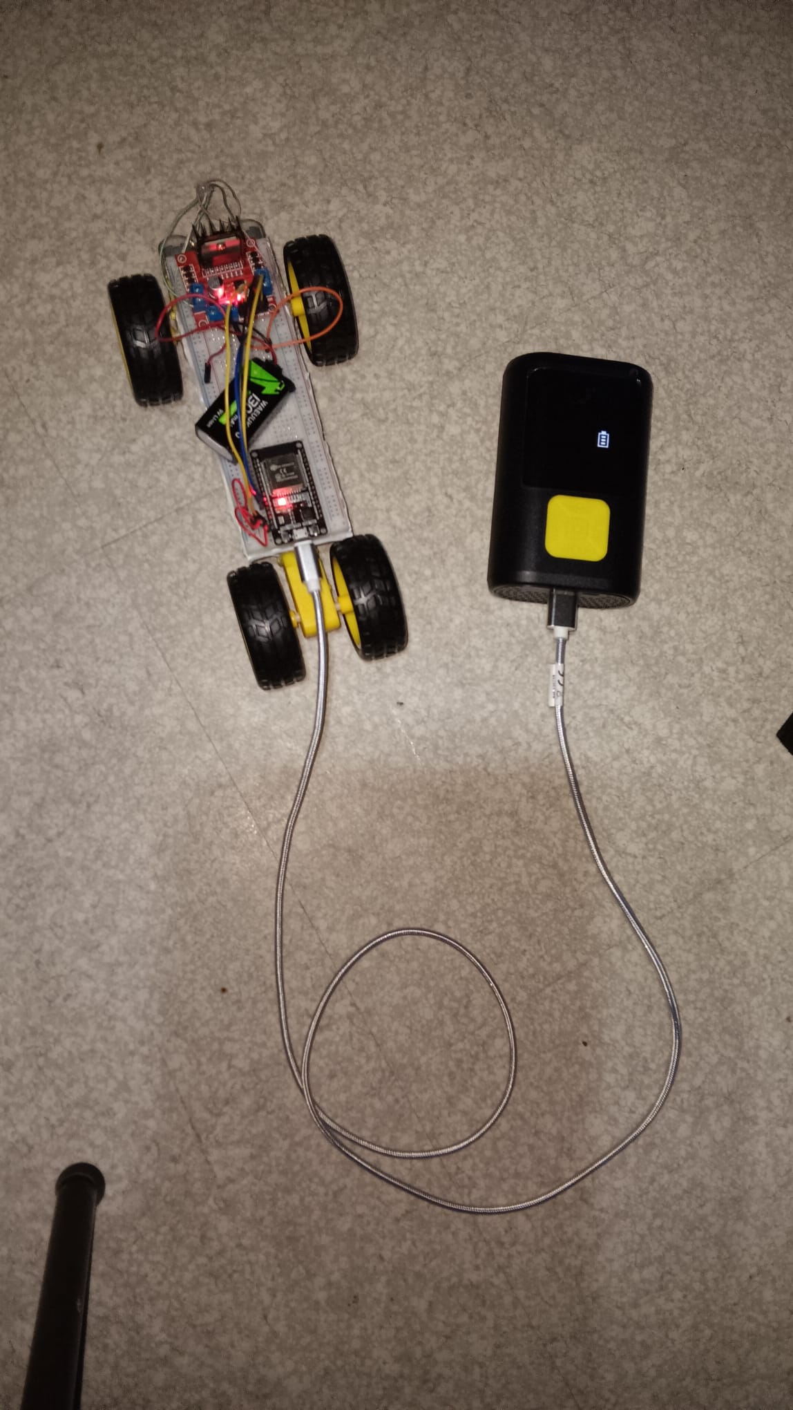
Now, everything works exactly as I want it to!
A Working Prototype
I really enjoyed the process of designing and building this system. It reminded me why I love engineering: successfully turning an idea into reality is an incredible feeling.
A few extra shots and clips from building the WIFI-Controlled Car.